Aeration systems for wastewater treatment do more than put air into a tank. They may supply oxygen, keep biomass or carrier media in motion, limit unwanted settling, or support a membrane operating cycle.
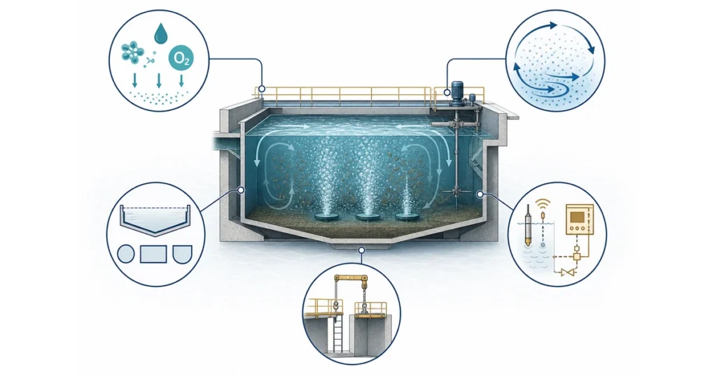
Aeration selection begins with process duty and operating conditions before equipment configuration.Selection begins with the wastewater load, biological process, required duty, basin geometry, operating range and maintenance conditions. This guide compares the main families and the information needed for an initial engineering review. Final sizing uses project-specific calculations and supplier data.
Quick Answer
There is no universal best aeration system. The main families are diffused aeration, mechanical or surface aeration, jet or ejector aeration, and specialized high-purity-oxygen routes. The initial choice depends on oxygen demand, mixing duty, actual wastewater transfer conditions, basin depth and geometry, turndown, fouling exposure, controls, maintenance access and the surrounding treatment train.
What an Aeration System Must Do in Wastewater Treatment
The first selection question is “What duties must the aeration system perform in this process?” Oxygen transfer and mixing often occur together, but each duty needs its own design check because the airflow or mechanical power required for one may not satisfy the other.
The U.S. EPA’s fine-bubble aeration fact sheet identifies oxygen supply and wastewater mixing as the two basic aeration duties.
Match Oxygen Supply to Process Load
Aerobic microorganisms use dissolved oxygen while converting biodegradable organic matter. Nitrification creates an additional oxygen demand when ammonia removal is part of the treatment target.
The required oxygen supply changes with flow, BOD load, ammonia load, temperature, biological solids, process configuration and operating conditions. Minimum, average and peak cases belong in the same review: sizing only around average load can leave insufficient peak capacity, while selecting only around the highest theoretical case can create inefficient low-load operation.
Maintain Mixing and Suspension
Mixing keeps biomass, wastewater and oxygen in contact and limits unwanted settling or dead zones. MBBR carriers need appropriate movement in aerobic zones, and lagoons or equalization basins may require broad-area circulation.
At low biological load, minimum mixing duty may control the airflow or mechanical power even when oxygen demand is modest. Tank geometry, equipment placement, process zones and inlet or recirculation patterns therefore remain part of aeration selection.
Separate Process-Specific Duties
The word “aeration” can describe several jobs:
| Duty | What to Establish | Design Consequence |
|---|---|---|
| Oxygen supply | Biological load, nitrogen target and actual wastewater conditions | Establishes required oxygen delivery across the load range |
| Mixing | Biomass or carrier suspension, tank geometry and dead zones | Establishes minimum circulation or airflow |
| Process-specific duty | MBR, MBBR, lagoon or equalization interfaces | Separates biological air from carrier, membrane or basin duties |
| Control | Minimum, average and peak demand, turndown and zoning | Establishes staging, measurement and operating flexibility |
One installation may combine several duties, but keeping them visible prevents one equipment rating from being used as a substitute for the complete process requirement.
Types of Aeration Systems and Their Tradeoffs
Wastewater treatment aeration systems can be organized into four practical families. Compare operating principle, process duty and site fit first.
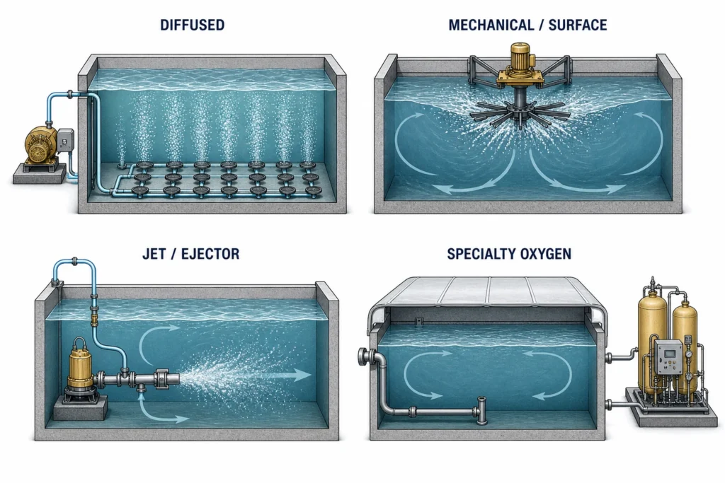
The four families use different gas-liquid contact and circulation principles; each still requires project-specific verification.Diffused Aeration
A diffused system uses blowers, air piping, distribution headers and submerged diffusers. Air released near the tank floor transfers oxygen as bubbles rise and also contributes to basin circulation.
Transfer potential depends on submergence, diffuser type and density, airflow per diffuser, wastewater characteristics, dissolved-oxygen conditions, fouling and air distribution. Grid layout, blower location, piping losses and access for cleaning or replacement are part of the system decision.
Fine-Bubble vs Coarse-Bubble Diffusers
Fine-bubble and coarse-bubble diffusers create different transfer, pressure, mixing and maintenance conditions. Final comparison uses the actual tank, water and airflow range.
| Comparison Factor | Fine-Bubble Diffusers | Coarse-Bubble Diffusers |
|---|---|---|
| Oxygen-transfer potential | Generally higher under suitable standard and field-corrected conditions | Generally lower, with performance depending on depth and arrangement |
| Mixing contribution | Minimum airflow may be governed by mixing at low oxygen demand | Larger bubbles can create more localized turbulence, but basin-wide circulation still requires verification |
| Air distribution | Grid density, balancing and airflow control are often critical | Header and diffuser spacing still affect distribution and dead zones |
| Pressure and headloss | Diffuser dynamic wet pressure and fouling can raise blower pressure | Gas paths are often less restrictive, although device losses remain configuration-specific |
| Fouling and cleaning | Small pores can be exposed to biological or chemical fouling and material attack | Larger openings may reduce pore-blockage exposure but still face deposits, scaling and material constraints |
| Maintenance and access | Cleaning method, grid isolation, retrievability and dewatering strategy need early planning | Device condition, header access and tank isolation remain important |
| Common evaluation context | Distributed oxygen demand in biological basins where transfer performance justifies the grid and maintenance scope | Mixing-heavy duties, digesters, sludge holding or wastewater conditions that favor a less restrictive gas path |
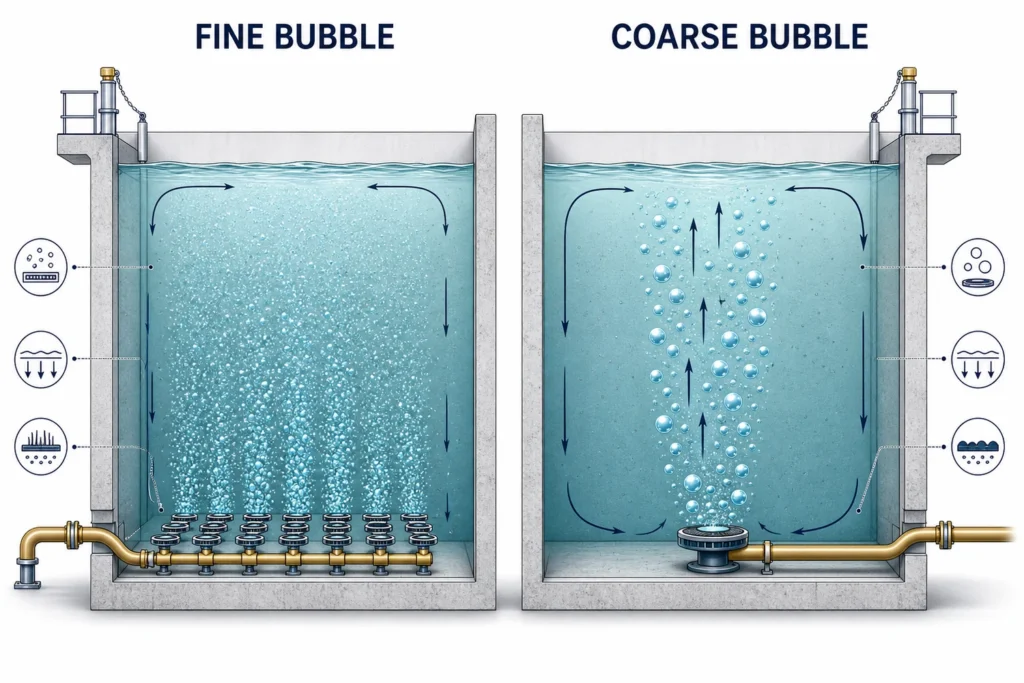
Bubble size changes transfer potential, turbulence, air distribution, headloss and maintenance exposure; actual performance depends on the complete system.Blowers and Air Distribution Are Part of the System
A diffused aeration system is an air-production and distribution chain: air intake and filtration, blowers, discharge piping, headers, zone valves, measurement points and diffuser grids.
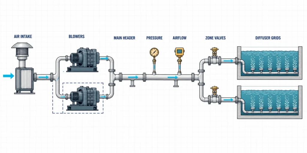
A diffused aeration system must coordinate air production, pressure, measurement, zoning and diffuser distribution.Required blower pressure includes water submergence and losses through piping, valves and diffusers. Fouling can raise dynamic wet pressure, so diffuser efficiency cannot compensate for an undersized blower, excessive pipe loss or uneven air distribution.
Depending on blower type and plant scale, output control may use staging, variable speed, inlet or guide-vane adjustment, pressure control, airflow control and zone valves. Airflow and pressure measurement help distinguish process demand from distribution or fouling problems. Standby capacity reflects the consequence of losing one blower or air zone. The Water Environment Federation’s blower guidance outlines common control strategies.
Mechanical and Surface Aeration
Mechanical systems use impellers, rotors, brushes or other agitation equipment to introduce atmospheric oxygen and create circulation. They are commonly evaluated for open basins, oxidation ditches and lagoons.
Water depth, basin shape, circulation path and operating range affect performance. Equipment support, moving parts, splash, aerosols, noise, cold weather and safe maintenance access belong in the site review.
Jet and Ejector Aeration
Jet and ejector systems combine pumped liquid circulation with gas-liquid contact through nozzles or related devices. They may entrain atmospheric air or use a separate gas supply.
The hydraulic and gas paths vary by equipment design. Pump duty, nozzle arrangement, gas flow, tank geometry, solids concentration, isolation and lifting access determine the actual fit. A jet, ejector or self-aspirating unit may be fixed, submersible or retrievable; “submersible” describes an installation arrangement rather than one aeration principle.
Pure-Oxygen and Specialty Routes
A pure-oxygen system uses high-purity or oxygen-enriched gas instead of relying only on atmospheric air. It may warrant feasibility review where oxygen demand is unusually high or basin constraints make conventional air-based alternatives difficult.
This route adds oxygen generation or storage, dissolution, gas containment or ventilation, controls, safety, supply continuity and operating expertise. The U.S. EPA technology assessment describes historical oxygen-activated-sludge configurations; current feasibility depends on technical, safety and economic review.
Initial Routes to Evaluate
| Initial Condition | Route Commonly Worth Evaluating First | What Still Needs Verification |
|---|---|---|
| Deep biological basin with distributed oxygen demand | Fine-bubble diffused aeration | Mixing, field correction, fouling, air distribution and grid access |
| Lagoon or open shallow basin requiring broad circulation | Surface or mechanical aeration | Depth, circulation pattern, climate, splash, aerosols and support structure |
| Tank requiring combined pumped circulation, mixing and gas contact | Jet or ejector aeration | Pump duty, nozzle arrangement, solids, gas path, isolation and lifting |
| High oxygen demand or constrained basin where air-based routes may be insufficient | Specialty oxygen-route feasibility review | Oxygen supply, dissolution, containment, safety, controls and lifecycle economics |
| Retrofit with limited shutdown access | Retrievable or accessible arrangements within a suitable family | Installation path, isolation, piping, lifting and available downtime |
These are starting routes for comparison. The selected system still has to meet oxygen and mixing duties across the full operating range and remain maintainable at the site.
How Aeration Duties Change Across Biological Processes
The same equipment can perform different jobs across biological processes. Defining the process first makes the comparison more meaningful.
Activated Sludge, MBBR and MBR
In activated sludge, aeration supports biodegradable-organic removal, nitrification where required, and mixed-liquor suspension. Clarification, sludge return, sludge wasting and upstream toxicity require their own process controls.
An aerobic moving bed biofilm reactor uses suspended carriers for biofilm growth. Aeration supplies oxygen and can help circulate the carriers. Carrier fill, retention screens, reactor geometry and process zoning affect the arrangement, while anoxic zones normally rely on mixing. For product-level configuration, evaluate an MBBR wastewater treatment system.
An MBR has a biological oxygen duty and may also have a separate membrane-related air-scouring duty. Membrane type, tank arrangement, cleaning sequence and supplier requirements determine the airflow split. The U.S. EPA’s membrane bioreactor fact sheet summarizes MBR design and operating considerations, while Motiva’s MBR wastewater treatment plant page covers product-level configuration.
Lagoons and Equalization Basins
Large or open basins introduce depth, circulation, climate and equipment-spacing constraints. An aerated lagoon may need both oxygen and broad-area mixing. An equalization basin may primarily need homogenization, solids control or prevention of septic conditions. The treatment objective determines whether oxygen transfer, circulation or both control the equipment choice.
High-Strength Industrial Wastewater
High biodegradable load can create a large aerobic oxygen requirement. Oil, solids, salinity, extreme pH, toxic compounds or poor biodegradability can shift the preliminary route toward pretreatment, anaerobic treatment or a combined process before final aerobic polishing.
| Process Context | Primary Aeration Duty | Additional Interface | Key Review Inputs |
|---|---|---|---|
| Activated sludge | Oxygen supply and biomass mixing | Clarification, sludge return and wasting | Load range, biological target, tank geometry and controls |
| MBBR | Oxygen plus carrier movement in aerobic zones | Carrier retention and downstream separation | Carrier fill, process zones, mixing and air distribution |
| MBR | Biological oxygen plus configuration-dependent membrane duty | Membrane cleaning, permeate and sludge management | Biological load, membrane requirements, airflow split and access |
| Lagoon or equalization | Oxygen and/or broad-area circulation | Weather, depth, dead zones and solids | Basin geometry, climate, treatment objective and mixing pattern |
Design Inputs That Change Aeration Requirements
Wastewater treatment aeration systems design begins with process conditions rather than a catalogue airflow. The design team establishes oxygen and mixing duties, applies field conditions, and then evaluates the operating range of the complete equipment system.
Flow, Load and Actual Wastewater
Compile:
- minimum, average and peak flow;
- operating hours and batch, intermittent or continuous discharge pattern;
- BOD, COD and the biodegradable fraction;
- ammonia and nitrogen-conversion target where relevant;
- wastewater temperature and expected seasonal range;
- short-duration peaks, cleaning discharges and known shock loads;
- future production or treatment-capacity changes.
Two plants with the same daily volume can impose different oxygen demands because wastewater strength, discharge pattern and treatment targets differ.
Transfer data are often reported under standardized clean-water conditions. Temperature, dissolved solids, surfactants, oils, suspended solids, viscosity, salinity and biomass change bubble behavior and oxygen transfer. Representative wastewater data and appropriate field corrections connect equipment test results to the project.
Basin and Site Conditions
The tank is part of the aeration system. Important inputs include:
- water depth, length, width and internal geometry;
- inlet, outlet, baffle and recirculation locations;
- process zones and required circulation paths;
- new construction versus an existing basin;
- space for blowers, pumps, lifting equipment and controls;
- air-piping route and expected pressure losses;
- inspection, cleaning, isolation and dewatering access;
- altitude, climate, ventilation, noise and aerosol constraints.
These inputs can change equipment placement, transfer path, air or liquid distribution, maintenance method and shutdown strategy.
Controls, Turndown and Engineering Basis
Low load may require staged or reduced output, while peak conditions may require additional capacity. Zoning can improve distribution flexibility when valves, instruments and control logic match the process and operator capability. Redundancy should reflect the consequence of losing oxygen supply or mixing in each treatment train.
Four terms organize the engineering basis:
- Actual Oxygen Requirement (AOR): oxygen required by the process under actual operating conditions.
- Standard Oxygen Requirement (SOR): transfer capacity expressed under defined standard conditions after applying field corrections.
- Standard Oxygen Transfer Efficiency (SOTE): an equipment transfer-efficiency measure under stated standard test conditions.
- Mixing requirement: the independent circulation or suspension duty in the actual tank.
The Water Environment Federation’s aeration design guidance explains how flow, load, field corrections, equipment transfer and mixing connect during design.
Where Aeration Fits in a Complete Treatment Train
Aeration supports a biological or mixing duty within a larger treatment route:
Screening / Equalization / Pretreatment → Biological Reactor + Aeration Duty → Solids or Membrane Separation → Polishing / Disinfection / Reuse → Sludge and Residuals Management
Aeration alone does not remove every pollutant class. Free oil, metals, dissolved salts, refractory organics, pathogens and separable solids may require physical, chemical, membrane or advanced-treatment steps.
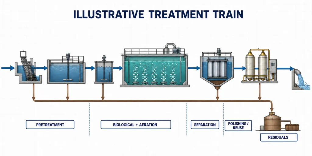
Aeration supports a biological or mixing duty between upstream conditioning and downstream separation; it is not the entire treatment route.Upstream Conditions
Depending on the wastewater, upstream treatment may:
- remove coarse solids and protect pumps or aeration equipment;
- equalize flow, pH and pollutant peaks;
- reduce free oil, grease or suspended solids;
- precipitate metals or manage corrosive chemistry;
- reduce inhibitory compounds or improve biodegradability;
- lower a high organic load before the aerobic stage.
Appropriate pretreatment can reduce foaming, fouling, sludge production, oxygen demand and biological instability. If the stream contains several pollutant classes, compare industrial wastewater treatment methods before assigning the biological stage.
Downstream Separation and Residuals
Biological treatment may be followed by clarification, membrane separation, filtration, disinfection, reuse polishing or concentrate management. Waste sludge, spent chemicals and other residual streams also need defined handling routes.
For a complete industrial route, review the industrial wastewater treatment solution. Buyers comparing system-level equipment roles can also review wastewater treatment systems and equipment.
Operating and Maintenance Factors to Compare
Lifecycle fit depends on energy, operating range, cleaning, access, downtime and wastewater exposure as well as initial equipment cost.
Energy and Control
Aeration is often a major electrical load in biological treatment. Matching oxygen delivery to process demand can reduce unnecessary airflow or mechanical output while preserving treatment stability. Control may combine equipment staging, adjustable output, air zoning and feedback from dissolved oxygen or other process measurements.
The control strategy should fit the load variation, instrumentation, operator capability and blower or aerator operating range. For broader CAPEX, OPEX and supply-boundary considerations, review wastewater treatment system cost factors.
Fouling, Access and Downtime
Fine-pore diffusers can accumulate biological or chemical deposits that change airflow distribution and pressure. Mechanical and jet equipment face different wear, nozzle, seal, solids and lifting requirements. Material selection also reflects corrosion, scaling, oil, temperature and cleaning chemistry.
The maintenance plan should establish how performance decline will be detected, whether equipment can be isolated or retrieved, whether the basin must be drained, which cleaning method and spares are required, and whether another train can remain in service.
| Review Area | Questions to Ask | Decision Effect |
|---|---|---|
| Energy and control | What is the load range, operating schedule, control method and local tariff? | Defines operating points and lifecycle energy exposure |
| Maintenance | Can equipment be isolated, retrieved, cleaned and supported with available spares? | Defines downtime, labor and service planning |
| Wastewater exposure | Is there fouling, scaling, corrosion, oil or high solids? | Influences materials, headloss, cleaning and wear |
| Site effects | Are noise, aerosols, ventilation, weather or limited access important? | Influences equipment location and maintenance method |
A Practical Aeration System Selection Framework
A preliminary selection can follow five steps:
- Define each duty. Identify biological oxygen, mixing, carrier movement, membrane-related aeration, basin circulation and any combined requirement.
- Establish the design cases. Compile minimum, average and peak flow and load, biological targets, wastewater temperature and chemistry, existing performance data and foreseeable expansion.
- Confirm process, basin and site constraints. Map process zones, tank depth and geometry, equipment locations, utilities, shutdown limits, climate and environmental conditions.
- Compare lifecycle fit. Evaluate transfer potential, mixing, turndown, distribution, fouling, maintainability, noise, aerosols, control complexity and energy under the project conditions.
- Verify the preliminary route. Apply project calculations, field corrections, supplier data and relevant test standards. Field measurement or treatability testing may be appropriate where wastewater behavior or existing-plant performance remains uncertain.
This sequence moves from process duty to equipment family and then to configuration. It also keeps upstream pretreatment, downstream separation and residuals handling connected to the aeration decision.
Data to Prepare for an Aeration Review
Send one set of project inputs through the Motiva RFQ / Water Data Form. We use the information to review the biological route, separate oxygen and mixing duties, identify basin and equipment interfaces, and define the questions that remain before detailed sizing or quotation.
Wastewater and Flow Data
- wastewater source and production process;
- minimum, average and peak flow;
- operating hours and discharge pattern;
- COD, BOD, ammonia, TSS, pH and temperature;
- oil and grease, salinity/TDS, surfactants, metals or other relevant pollutants;
- sampling dates and available laboratory reports;
- known shock loads, cleaning chemicals and seasonal changes.
Treatment and Process Target
- required discharge, reuse or downstream-treatment target;
- existing or proposed biological process;
- organic-removal and nitrogen-removal objectives;
- upstream pretreatment and downstream separation;
- current operating problem for a retrofit;
- planned production or capacity expansion.
Basin, Utility and Operating Data
- basin dimensions, operating water depth and layout;
- existing diffusers, aerators, blowers, pumps and air piping;
- available airflow, pressure, dissolved-oxygen and energy records;
- electrical supply, instrumentation and control system;
- access, lifting, tank-isolation and shutdown conditions;
- climate, altitude, ventilation, noise and aerosol constraints;
- redundancy, spare-parts and operator-maintenance requirements.
Representative sampling, field measurements, equipment data and local discharge or reuse requirements can then be added where the preliminary review identifies a specific information gap.
Frequently Asked Questions
What Does an Aeration System Do in Wastewater Treatment?
It supplies oxygen, mixing or both for the selected treatment process. Depending on the configuration, it may also support carrier movement, membrane operation or broad-basin circulation.
What Are the Main Types of Wastewater Aeration Systems?
The main families are diffused aeration, mechanical or surface aeration, jet or ejector aeration, and specialized high-purity-oxygen routes. Fixed, surface, submersible and retrievable arrangements describe how equipment may be installed or serviced within those families.
What Is the Difference Between Fine-Bubble and Coarse-Bubble Aeration?
Fine-bubble diffusers generally offer greater oxygen-transfer potential under suitable conditions, while coarse-bubble diffusers use a less restrictive gas path and may provide more localized turbulence. Actual selection also considers mixing duty, air distribution, headloss, fouling, materials and maintenance access.
Which Aeration System Is Best for Wastewater Treatment?
The appropriate system meets oxygen and mixing duties across the load range while fitting the basin, wastewater, controls and maintenance conditions. The table above offers a starting comparison.
How Are Aeration Requirements Calculated?
The design starts with minimum, average and peak process oxygen demand. Appropriate field corrections convert actual requirements and equipment test conditions to a common basis. Mixing, turndown, pressure, distribution, redundancy and site constraints are then checked alongside oxygen transfer.
How Is Aeration Different in MBBR and MBR Systems?
An aerobic MBBR may use aeration for oxygen supply and carrier movement. An MBR has a biological oxygen duty and may also have a separate membrane-related air-scouring duty, depending on the membrane configuration and operating strategy.
Can Aeration Remove Oil, Heavy Metals or Dissolved Salts?
Aeration is normally part of the biological or mixing stage. Oil, metals, dissolved salts and other non-biodegradable or separable pollutants require the appropriate pretreatment, separation, membrane or advanced-treatment route.
What Data Is Needed Before Reviewing an Aeration System?
Provide flow and load ranges, water-quality data, treatment targets, process type, basin dimensions, utilities, existing equipment information and operating or maintenance constraints.
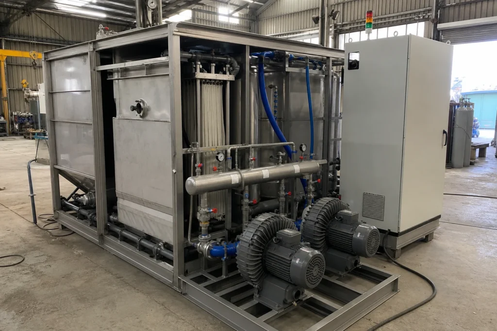
Illustrative configuration showing how blowers, air distribution, biological treatment components, controls and maintenance access may be integrated; actual Motiva equipment is project-specific.Review Your Aeration and Treatment Route
If you are planning a biological treatment system, expanding an existing plant or investigating an aeration problem, send the available water-quality, flow, basin and operating information.
We can review how the aeration duty fits within the biological process and the complete treatment route, then identify the next calculations, measurements and equipment-scope decisions.
Send Water Data for Aeration and Treatment Route Review
Sources and Technical References
- Water Environment Federation — Liquid Stream Fundamentals: Aeration Design
- Water Environment Federation — Liquid Stream Fundamentals: Blowers
- U.S. EPA — Wastewater Technology Fact Sheet: Fine Bubble Aeration
- U.S. EPA — Evaluation of Energy Conservation Measures for Wastewater Treatment Facilities
- U.S. EPA — Membrane Bioreactors, Wastewater Management Fact Sheet
- U.S. EPA — Innovative and Alternative Technology Assessment Manual